Rigid-Flex and Flex PCBs
Rigid-Flex PCBs can be used in a variety of different applications, from electronics to medical devices. Due to their design, these boards are able to withstand mechanical stress and vibrations. They can also be bent and curved to fit the final product. In order to avoid issues during manufacturing and assembly, there are a few key things that engineers need to consider when designing rigid-flex circuits.
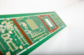
Rigid PCBs are made of woven fiberglass impregnated with epoxy resin. This makes them rigid, but they also have some elasticity due to the cured epoxy. Rigid PCBs are the most common and well-known type of printed circuit board. They are used in a wide range of electronic products, including mobile phones, laptop computers, and tablets. Rigid-flexible pcb board are also becoming increasingly popular due to their unique properties.
Flex PCBs are made of polyimide, which is extremely flexible and tough. It’s able to be rolled or twisted without damaging it, and it can withstand several solder reflow cycles. In addition, it’s tolerant of expansion and contraction caused by temperature fluctuations.
Key Differences Between Rigid-Flex and Flex PCBs
While the material is durable, a flex PCB still requires careful handling to ensure that it doesn’t get damaged or broken. In general, it’s recommended to avoid placing any components or connections that are likely to come into contact with the flex area of the board. This will help prevent the copper traces from being exposed to excessive stress, which can lead to failures and malfunctions.
The flex-rigid transition zone is the area where the rigid portion of the PCB meets the flex section. It can be a tricky spot to design, especially when it comes to signal transitions between the rigid and flexible sections of the board. Improper layer transitions can cause signal integrity issues and electromagnetic interference (EMI). Additionally, it’s important to place connectors away from the flex region in order to avoid mechanical stress.
When it comes to a flex-rigid PCB, the copper traces are typically thinner than those on rigid PCBs. This allows for greater flexibility, but it can make it difficult to maintain high-speed signals. To overcome this, designers can use air gaps to separate the layers and create space for the traces to move freely.
It’s also important to minimize the number of vias on a flex-rigid PCB. Vias that are placed in the bend area of a flex-rigid PCB are susceptible to cracking, or “lifting.” This is a result of mechanical stress and pressure on the copper traces. In order to reduce the risk of this, it’s recommended that you use room designs to identify areas where there won’t be any bends and limit via a placement to those regions.
Another factor that influences the cost of a flex-rigid or a flexible PCB is the number and size of the drilled holes. Smaller drill holes require more specialized tools and are more costly than larger holes, and tracing spaces that are too tight can increase costs as well.